February 16, 2016 (with later updates)
This page documents some very basic digital logic devices I've built.
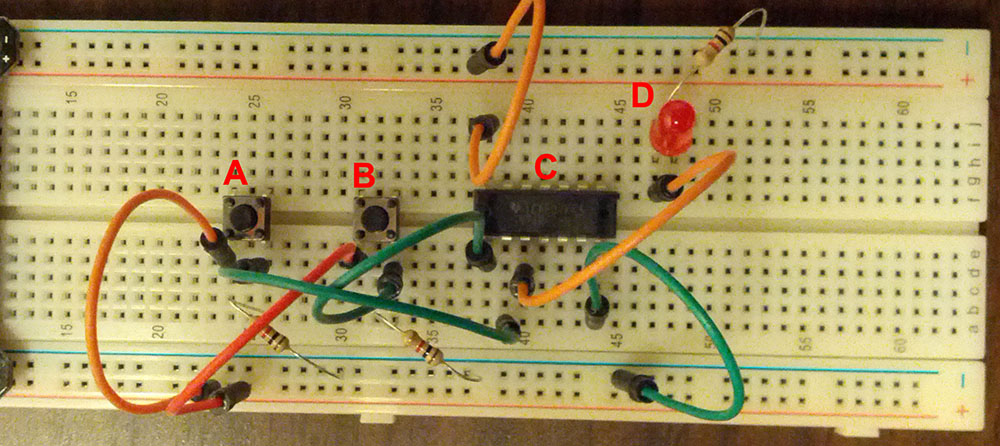
This is a schematic of a full adder, copied shamelessly from the internet. (The gate marked with an asterisk can be either an OR or an XOR gate, with no effect on behavior.)
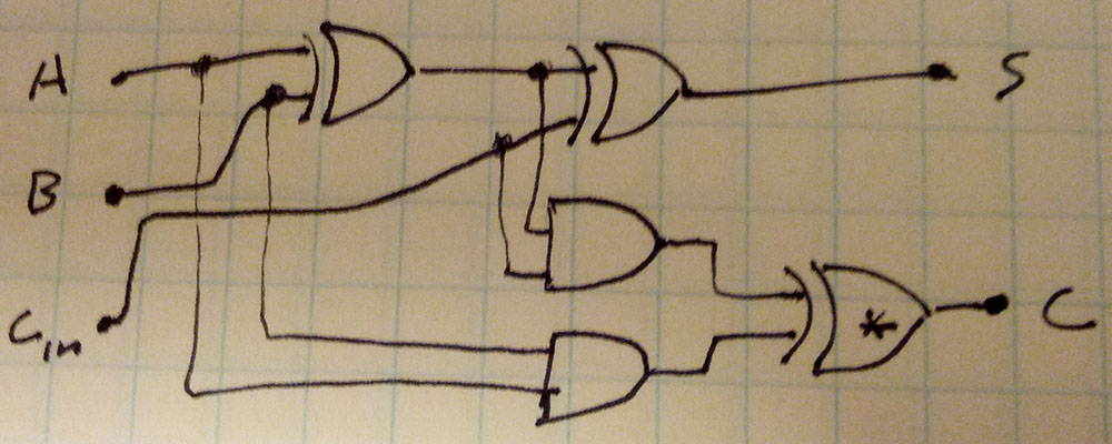
My implementation uses three chips, but a full adder requires only five of the 12 gates in those chips.
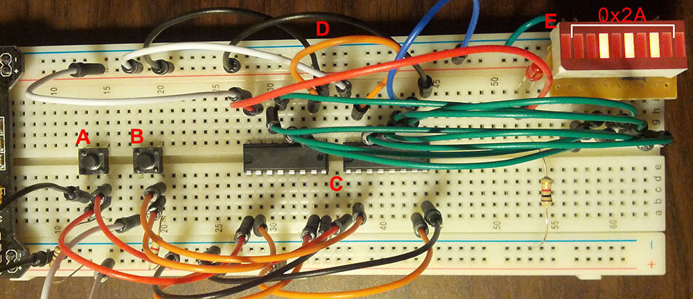
HIGH if at least two of the inputs are HIGH.This is just a simple circuit to exercise the functionality of a 74HC161 4-bit counter. A major flaw of this circuit is that the "increment" button, A, is not de-bounced, so the counter will often increment more than once when the button is pressed. I had no capacitors when I assembled this circuit, so I couldn't fix this.
1111.February 19, 2016
This circuit demonstrates how 74HC161 counters can be chained to create larger counters. In this case, two 4-bit counters are combined to create an 8-bit counter.
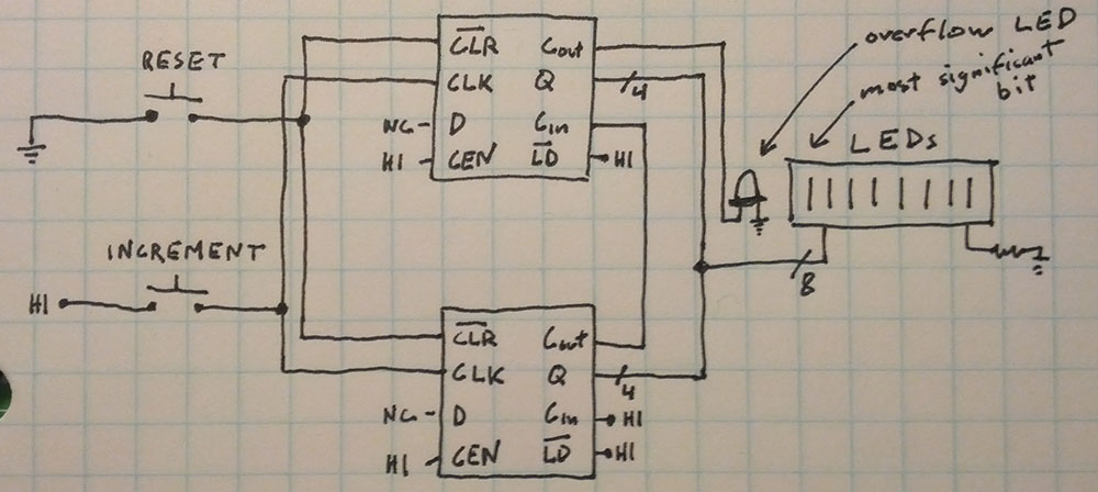 Notably, the best way to do this is to connect the "carry out" pin on the first counter to the "carry in" pin on the second counter -- not to its clock pin! Sending the "carry out" to the clock pin will work, but it makes it difficult to also use the load functionality, which is synchronous. (In the datasheet, the "carry in" pin is called CET -- "count enable trickle" -- which does not make its significance clear.)
February 23, 2016
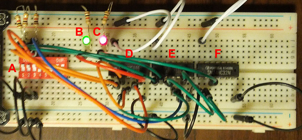
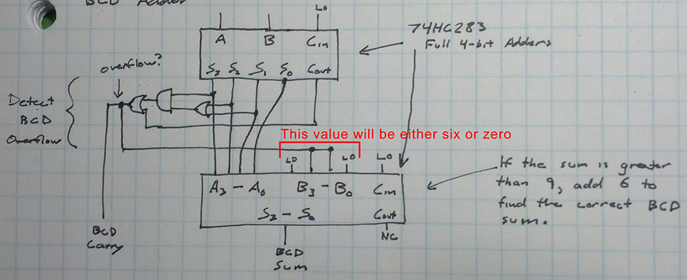
This circuit demonstrates the 74HC283 4-bit Full Adder. This chip adds together two 4-bit binary values and produces a 5-bit sum. (The fifth bit is the carry-out bit, which could be chained to another adder.)
February 23, 2016
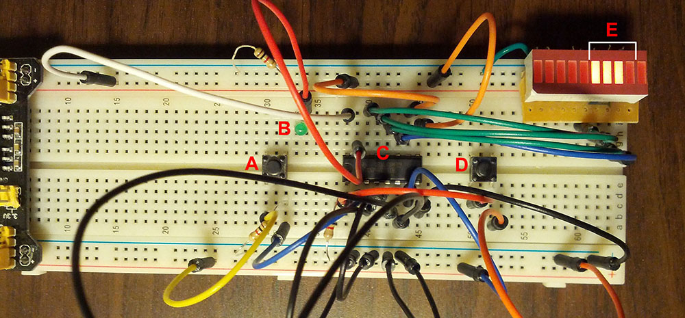
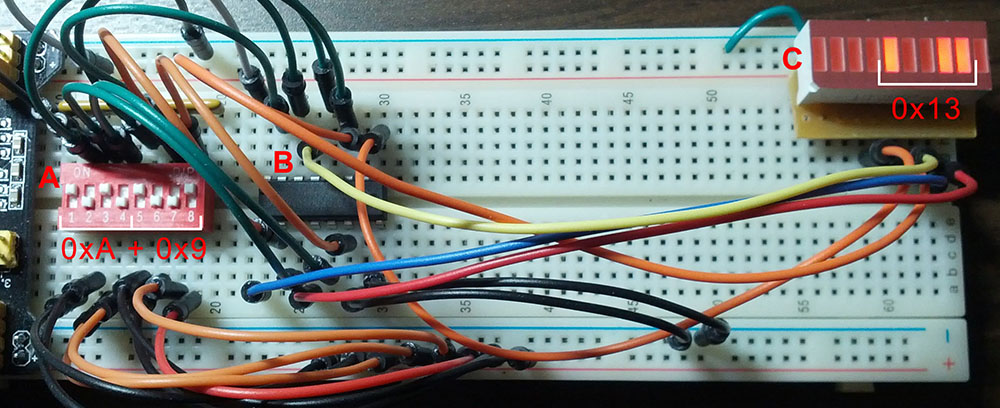
This circuit adds together two 4-bit BCD digits, producing a BCD sum and a carry bit. It works as follows:
The input values must be valid BCD digits between zero and nine. Add the input values together with ordinary two's-complement addition. This intermediate sum will be between 0 and 18.
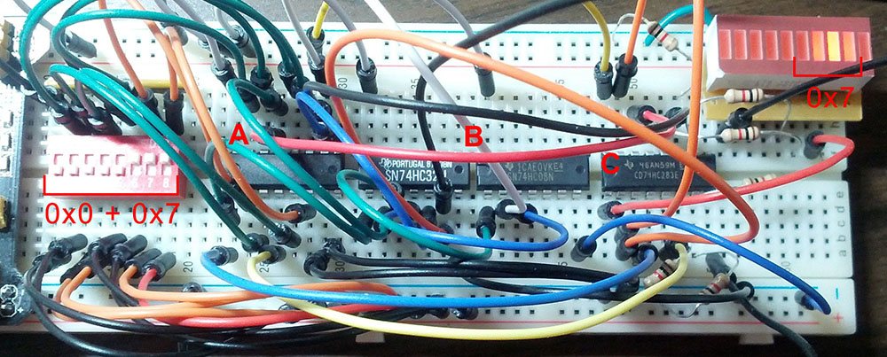
In this photo, 0 + 7 = 7 is calculated. Since the result is not greater than nine, it behaves just like binary addition and there is no overflow.
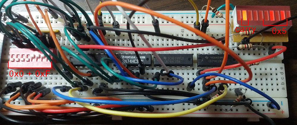
In this photo, 0 + 15 = 15 is calculated. (This isn't valid input to a BCD adder, but the result in this case is no different than adding 8 + 7.) Since the sum is greater than 9, the BCD overflow detector kicks in, enabling carry-out and adjusting the sum to properly wrap around from nine to zero.